
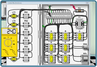

PLC troubleshooting and diagnostics
Programmable Logic Controllers problems(PLC)
Learn how to troubleshoot and diagnose PLC's with this procedure and how to identify the PLC problem areas.
-
Identify where the PLC problem might be with certain Inputs or outputs etc.
-
Check to ensure main PLC power is being applied (120vac or 24vdc) many times their is a main power LED on the PLC to indicate so. Also check that it is the correct voltage being applied.
-
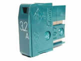
Check the 24VDC power supply that may be either provided internally from the PLC itself or by an external power supply. Also check no primary fuses are blown.
-
Check the 120VAC supply or transformer is outputting correct voltage and no fuses are blown. This is often used for hydraulic solenoid coils and such.
-
Look for the area of the cell or sensors and switches located in the problem area. Such as a tool changer, pallet changer or magazine area. Look through the electrical prints for the possible proxes or devices that may be faulty.
-
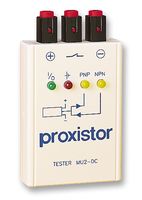
Check each input LED goes on on the PLC or on the internal control diagnostics. Manually make each of the switches. Put the machine in ESTOP to avoid any unexpected movements. But still be careful as some ladders are not written fully safe. Remember proxes typically fail to the on state so make sure they are not on when they are not supposed to be as well.
-
Check the inputs on the machine or PLC diagnostics as you make and break them. If these are all working correctly move on to checking the outputs below. Otherwise test that power is coming back into the PLC inputs with a meter.
-
At this point it may be necessary to actuate the machine either by an M-code if it is a CNC or if it is a PLC direct then run the functions you are trying to perform.
-
Determine possible solenoids or outputs that should be turning on for each condition and monitor when actuated. Now check the output LED's or Y addresses to see if plc or control is outputting them.
-
If the outputs are being turned on by watching the diagnostics or LED's. Verify with a meter the proper voltage is coming out of the PLC and verify the proper voltage is at the solenoid. Many PLC outputs often go through a relay of some sort to change over to 120 volts. Make sure you check the voltage at the relay coil as well as the supply being but to the dry set of contacts on the relay. Make sure the relay switches when the PLC output is turned on.
-
Many times these relay boards will have a relay go bad or have a device such as a solenoid that shorts out to ground causing the relay contact to burn up. There are also sometimes fuses in the circuit as well that may need to be checked.
-
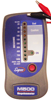
If the relay contact is found to be bad. Check with your meter and the power off to ground from the circuit that may be shorted. If its less then 40 ohms or so you most likely have a short to ground. Find the short or bad coil and repair. Then sometimes another relay may be swapped out that was not being used on the board Many times you have to unsolder and resolder in the bad relays place
-
Some PLC's if they are for automation or external fixtures sometimes have a reset on them to clear and major alarms inside the PLC itself. But you generally would have a complete shut down of PLC functions if this were the case. Use caution on mushing any buttons on PLC's.
Notes on voltage range to expect when testing PLC logic circuits.
The 120 volt circuit should not drop below 100 volts for any reason if it does there is a problem.
If the 24VDC power or measurement reading is less then 20VDC then there is also most likely a problem with this circuit. the power supply should always output 23 to 25 volts. If it is not main machine transformer taps or power being applied to primary may not be set properly.