CNC Machine Help-Home

Automation/Machine options
What will you need?
Rotary Indexer selection
High pressure coolant
Oil Skimmers & separators
System integrator selection
Robotics interfacing
Fixture design / interface
Hydraulic pump design
Fixture automation checks
Tool breakage detection
Light curtains & safety
Planning automation projects

Interface, design, integrate
Panel design & layout tips
HMI examples
Ladder logic examples
Stepper verses DC servo
Position encoder types
Sensor switch selection
Hydraulic pump design
Fanuc ladder modify/edit


**CNC help Forums**
Newest recent content
CNC Books Store
CNC Specialty STORE (New!!)

Classifieds (buy/sell-Free)
Search

Newsletter sign up

Free trade magazines


Tool Breakage Unit Detection SystemsTool breakage unit detector setup


This will show you how to detect broken drills, mills and other tooling with positive contact type sensors. What are your options and what should you consider before buying tool breakage detection and automating your machine tool? Prevent excessive scrap parts and rework with little if any loss of cycle time. Prepare for lights out operation. Check cylindrical shank cutting tools such as drills, taps, reamers or specialty form tools on CNC lathes, machining centers, multi-spindle screw machines, and chuckers.

Error proofing using tool breakage system applications:

  1. Broken tool detection
  2. Part seated properly
  3. Part clamped
  4. Check position or general location
  5. Sense hole depth or operation completed (Plunger)

Types of tool breakage detection systems:

  1. Basic scanning wand- detects whether the wand reaches end of stroke.
  2. Built in encoder scanning wand- can learn different tool lengths or positions.
  3. Plunger type tool breakage unit- detects whether the wand reaches end of stroke.

Tool breakage mounting considerations and detection:


Basic model Mounted on the pallet:

When mounted in the machining area, the spindle is programmed to the proper location to comp, for what ever tool length is present in the spindle. Minimal cycle time is lost.

Basic model Mounted in magazine:

If the tool sensor is mounted in the magazine, it will be used at a fixed position and can't be used for multiple tools. This is because tool lengths vary and have no axis to move the tool into the proper location.

Built in encoder type:

This has the ability to learn 30+ different tool lengths in a CNC tool changer. This unit can be mounted in the magazine area with little or no loss of cycle time. However, each tool must be taught positions and must have separate M-codes for every tool in order to recognize the different tool lengths. If mounted in the work envelope, then you should go with the basic model and program the axis to the location you would like to check the tool length. Unless you are using it to check position of parts or using it for a different application.

Plunger type tool breakage unit:

This is used for areas where the basic model can not be used. Also, this could be used for sensing hole depth or whether an operation was completed.
Here are some common well known tool breakage manufacturers:

  1. BK micro

  2. TPS International


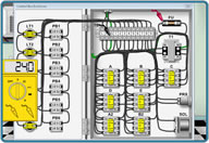
Installation and requirements:

M-codes or source of actuation is needed. The feed hold circuit is generally tied into or an external alarm is used to stop machine operation. A remote module is installed in the electrical cabinet. If the unit is mounted on the pallet, a cable is run down through the cable tracking and possibly through the way cover.


Share your CNC information?
...Procedures
...Macro programs
...Experience
...Stories
...Articles
...Recommendations
...Anything related

Suggestions or comments?
Please Email Me: petro@machinetoolhelp.com

Thank you for all your contributions and supporting the CNC community.


.